
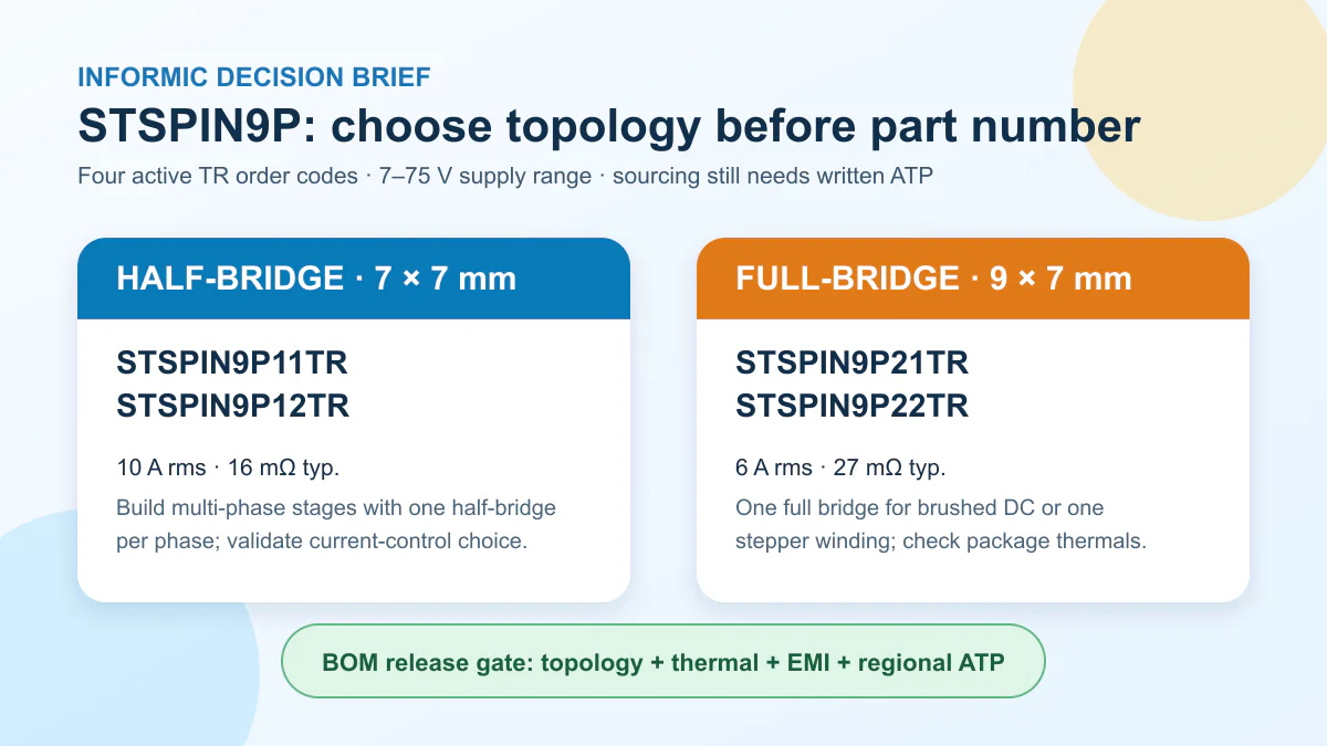
The short answer: STMicroelectronics introduced the STSPIN9P family on October 1, 2026, and four tape-and-reel order codes now deserve a controlled design-in review: STSPIN9P11TR, STSPIN9P12TR, STSPIN9P21TR, and STSPIN9P22TR. Motor-control engineers must choose the half-bridge or full-bridge architecture before comparing part numbers. Buyers should ask for written regional ATP, lead time, MOQ, date-code, and price evidence before releasing any production BOM. “Active” is a lifecycle signal; it is not a delivery promise.
What changed on October 1
ST published its STSPIN9P launch article on October 1, 2026. The manufacturer describes the family as its first 75 V high-current motor-driver platform in compact 7 × 7 mm and 9 × 7 mm QFN packages. The public portfolio spans half-bridge and full-bridge devices with integrated MOSFETs, current-sense circuitry, adjustable slew rate, protection functions, and open-load detection. That combination is relevant to factory automation, robotics, building systems, pumps, and power tools where board area and protection coverage matter.
The announcement is useful because it turns a family-level launch into a design question: which topology, control behavior, and loss profile fits the load? It does not establish regional stock, a production allocation, or a contract price. That distinction matters. The right immediate action is an engineering screen followed by an RFQ, not an uncontrolled AVL addition.
The four exact order codes in today’s review
ST’s live product pages list all four base products as ACTIVE and expose the complete TR tape-and-reel codes in their Sample & Buy tables. The suffix belongs in the BOM and RFQ; a family name or unsuffixed base number is not enough for an executable order.
| Orderable MPN | Topology | Package | Headline rating | Decision point |
|---|---|---|---|---|
STSPIN9P11TR |
Half-bridge | 7 × 7 mm VFQFPN | 10 A rms; 16 mΩ typical RDS(on) | Integrated current-limiter path |
STSPIN9P12TR |
Half-bridge | 7 × 7 mm VFQFPN | 10 A rms; 16 mΩ typical RDS(on) | Comparator available to the application |
STSPIN9P21TR |
Full-bridge | 9 × 7 mm VFQFPN | 6 A rms; 27 mΩ typical RDS(on) | Integrated current-limiter path |
STSPIN9P22TR |
Full-bridge | 9 × 7 mm VFQFPN | 6 A rms; 27 mΩ typical RDS(on) | Comparator available to the application |
All four product pages describe a 7–75 V supply range. The odd-numbered variants use the comparator in the current-limiting function; the even-numbered variants leave it uncommitted for the application. That is a functional choice, not a procurement preference. Firmware, shunt selection, fault strategy, and the verification plan may change with it.
A live page check on October 2 found an especially important sourcing boundary. The STSPIN9P11TR table displayed a USD 2.31-per-1,000 budgetary figure and links to three distributors, while the other reviewed pages displayed no distributor availability. This is a volatile manufacturer-page snapshot. It does not prove stock in the target country, that 1,000 pieces can ship, or that the displayed budgetary figure is a quotation.

Engineering choice: topology first, headline amperes second
The 10 A half-bridge parts are building blocks. A three-phase BLDC or PMSM stage normally needs three controlled legs, so the designer must account for three drivers, shunts, routing, decoupling, and synchronized protection behavior. The 6 A full-bridge parts integrate two legs and fit a brushed-DC motor or one stepper winding more naturally. Comparing “10 A versus 6 A” without counting the required bridge structure gives purchasing a misleading picture of cost and board area.
RDS(on) is also a starting value, not a thermal conclusion. The 16 mΩ and 27 mΩ figures are typical headline values. Real conduction loss depends on current waveform, duty cycle, recirculation path, switching frequency, junction temperature, PCB copper, vias, airflow, and simultaneous channel activity. Engineering should calculate worst-case loss with datasheet limits and then confirm it on the intended layout. A prototype that stays cool on an open bench can still fail inside a sealed enclosure or under a stalled-load transient.
The adjustable slew-rate feature gives the team a useful EMI/efficiency control, but it creates a test obligation. Faster edges can reduce switching loss while increasing ringing and radiated noise; slower edges can quiet the board while adding switching loss. The correct setting belongs to the real motor, harness, DC bus, enclosure, and EMC target. It cannot be approved from the launch announcement alone.
Any alternate device should be recorded as a candidate that requires validation. No pin-to-pin or functional substitute is approved by this review. Even within STSPIN9P, moving from an odd to an even suffix changes comparator use; moving between 1x and 2x changes topology and package. Treat those as engineering changes.
A practical qualification and sourcing gate
- Freeze the electrical architecture. Document bus range, nominal and peak phase current, motor type, PWM strategy, braking or regeneration conditions, shunt value, and whether the integrated current limiter or an application-controlled comparator is required.
- Run the thermal model. Use worst-case resistance and ambient conditions, not only the typical marketing value. Define copper area, thermal vias, airflow, enclosure temperature, and pass/fail junction margin.
- Test switching and faults. Tune slew rate on the real PCBA. Verify startup, stall, short-circuit response, overcurrent protection, UVLO, thermal shutdown, open-load detection, and recovery behavior.
- Close the supply evidence. Ask ST or an authorized distributor for target-region ATP, sample quantity, production MOQ, tape orientation, country of origin, acceptable date code, lead time, price breaks, and whether the quotation is allocation-backed.
Keep sample approval and production approval separate. A free sample or estore link proves access to an evaluation path, not repeatable production supply. Conversely, a written production quote does not replace electrical qualification. Both records should be attached to the same controlled BOM decision.

Facts, judgment, and recommendations
Verified facts: ST dated the launch article October 1, 2026. The four official product pages identify the base products as ACTIVE and expose the exact TR order codes. ST states a 7–75 V range, half-bridge and full-bridge options, typical 16 mΩ or 27 mΩ RDS(on), integrated current sensing, adjustable slew rate, protection functions, and open-load detection.
Engineering judgment: topology, comparator use, thermal margin, and EMI tuning are the decisive design-in questions. The typical resistance and rms-current figures are not sufficient to release a PCBA.
Procurement recommendation: keep the four MPNs separate in the AVL, request written target-region evidence for each selected code, and do not translate an ACTIVE badge, budgetary price, sample link, or distributor link count into confirmed ATP. No shortage, price trend, or lead-time improvement is claimed here.
If you are evaluating these drivers, send the motor requirements, controlled BOM, forecast, target region, and thermal or EMC constraints through the Informic contact page. We can support a line-item engineering review, PCBA sourcing check, and an updated quotation request without treating an unvalidated candidate as an approved replacement.
FAQ
Are STSPIN9P11TR and STSPIN9P12TR interchangeable?
They share the half-bridge platform and headline electrical figures, but the comparator function differs. Treat any swap as a candidate that requires schematic, control, fault-response, and bench validation.
Can an ACTIVE status be used as ATP evidence?
No. ACTIVE describes manufacturer lifecycle status. Production ATP requires a written, region-specific quantity and delivery commitment from ST or an authorized channel.
Does the 10 A rms rating guarantee 10 A in my enclosure?
No. Achievable current depends on temperature, PCB copper, vias, airflow, switching behavior, duty cycle, and the datasheet’s test conditions and limits.
Why keep the TR suffix in the BOM?
The suffix identifies the orderable tape-and-reel configuration shown by ST. Omitting it can create ambiguity in RFQs, packaging, and production intake.
Is a full-bridge STSPIN9P2x a drop-in substitute for a half-bridge STSPIN9P1x?
No. The topology, package, current rating, and intended motor architecture differ. It is a redesign candidate, not an approved substitute.
Sources
- STMicroelectronics, “STSPIN9P: ST’s first 75 V high-current motor drivers,” published October 1, 2026.
- STMicroelectronics official STSPIN9P11 product and Sample & Buy page.
- STMicroelectronics official STSPIN9P12 product and Sample & Buy page.
- STMicroelectronics official STSPIN9P21 product and Sample & Buy page.
- STMicroelectronics official STSPIN9P22 product and Sample & Buy page.
